Calculating the Angle of View: When Theory Meets Practice
Over the years, my depth of field calculator has slowly gained complexity into what it is now. One of the additions I added more recently was to calculate the angle and field of view for the specified lens on the specified sensor.
In the last couple of months I’ve received a few questions asking why the calculated angle of view doesn’t match the actual angle of view people see in their cameras.
The short answer to this is that it’s complicated. In fact, it’s actually very complicated.
For the longer answer, read on.
The Simplest Model
My angle of view calculations, started with a very simple model. All of the details of the optics involved are ignored. Only the focal length and sensor’s dimensions are used to compute the angle of view.
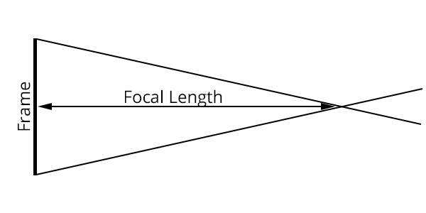
Fundamentally, the angle of view is the vertex angle of the isosceles triangle formed where base is the sensor’s height, width, or diagonal, and the vertex is at a point 1 focal length away from the sensor.

Perhaps surprisingly, this simple model actually works. Well, at least to an extent.
For any lens focused at infinity it will be pretty close. The only errors will be due to distortion and errors in the published focal length or sensor dimensions. In fact, for lens designed to not breathe while focusing, it remains accurate over most if not all of the lens’s focusing range.
However, it’s a simplistic model, and ultimately it will fail to reflect reality.
The model’s first major problem is that the effective focal length never changes as the lens focuses.
All one has to do is look at any inexpensive 50 mm prime and notice that when you focused closer than infinity, the lens shifts away from the camera. This shift is changing the effective focal length and with it the angle of view[1].
Refining the Model: Extension Effected Focal Length
If the effective focal length changes as we focus, then the question becomes can the model be improved to take that into account?
The answer to that is that it gets complicated.
For overall extension lenses, those that move all the elements when they focus, it’s actually both possible and fairly straight forward to solve. The effective focal length is the same as the image distance, which is related to the object distance (where you’re focusing) and the focal length by the following formula.
With that we can replace the focal length in the simpler angle of view model, with the image distance/effective focal length from the above equation, and the simple model deals with focusing closer than infinity.
Only there’s a problem here.
All overall linear extension lenses, by virtue of physics, have to obey the above formula. However, internal focusing lenses do not.
Designs for internal focusing lenses can pretty much do whatever their designers want them to do. For example, cine and video lenses are designed to hold the angle of view, and thus the effective focal length, constant while focusing.
Conversely, in my experience at least, most internal focusing still photography lenses will often shorten their effective focal length (widening the angle of view) as they focus closer[2].
Ultimately there are two problems here, at least in so far as I’m concerned as someone writing a angle of view calculator.
One is that compensating for the shift of an extending lenses, generally does the wrong thing for an internally focusing lenses. My solution to this problem was just to include both calculations, a note for which calculation to select for your lens, and a let the user pick the best value for their purposes.
The other problem is far more intractable.
Every internal focusing lens will have a different amount of effective focal length shift. This will depend entirely on what the design goals for that lens were, and how much effort the designers put into holding the angle of view constant.
Video and cine lenses almost universally tend towards having very little or no shift in focal length. Still photography lenses may have quite a lot or not so much depending on how other design considerations play out.
Since there’s no overriding formula that governs how an internal focusing lens will behave, the only way to deal with this in an angle of view calculation would be to know the behavior of a given lens design.
Moreover, in the case of a zoom lens, it’s not guaranteed that the same lens will behave the same way at either extreme of the zoom position.
For example, the published specifications for Canon’s EF 24-70mm f/2.8L II USM for field of view at 380 mm (1.25 ft) focusing distance are 554 x 369 mm at the 24 mm zoom position and 202 x 134 mm at the 70 mm zoom position.
At 24mm my calculator’s method straddle the actual results. The fixed angle of view method is about 3% too wide, and the linear compensation method is about 4% too narrow.
At 70mm both methods are too narrow, by 3.5% and 27% for the constant angle and linear extension compensation methods respectively.
Still More Complexity: Close Focusing, When Size Matters
Even ignoring that there’s no general solution for the problem of internal focusing lenses, the problems of calculating the angle of view of a lens still isn’t completely dealt with.
At long focusing distances we’ve been able to ignore the physical presences of the lens itself.
The simplest model doesn’t even “consider” there to be a lens involved at all, only a focal length to set a point for a triangle. At best, you could basically say that these simple models use the thin lens approximation.

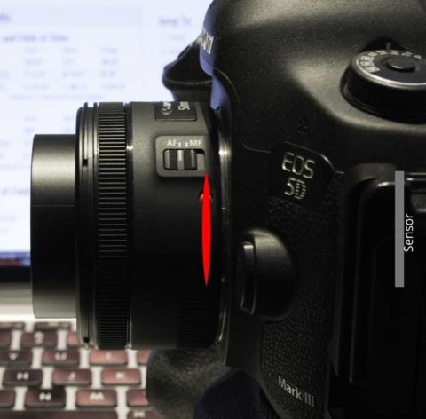
Note, lens is focused at minimum focusing distance though the approximate lens position isn’t completely correct.
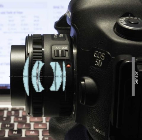
In reality, however, lenses are anything but infinitely thin symmetrical things. They have depth. More importantly, they’re almost always not optically symmetrical and stick out in to the world they exist in.

Note, lens is focused at minimum focusing distance.
At long subject distances, this can be ignored because the size of the lens is so much smaller than the focusing distance, that what little error it imparts isn’t material.
However, as subject distance drops, the lens’s physical size becomes larger in proportion to the focusing distance and therefore becomes a more significant factor in the calculations.
Again, mathematically it is possible to calculate the impact of the lens’s size and optical asymmetry on the effective focal length and the angle of view. However, the same problem exists here as it does with developing a general solution to the internal focusing lens problem. To calculate the error imparted by the size and asymmetry of the lens, you need to have information about specific lens designs not just something generalized.
And ultimately, as with the problem with internally focusing lenses, I don’t see a solution that’s feasible to implement without an absolutely prohibitive amount of work in testing every possible lens ever made (or at least that I want to support).
So what does all of this mean for the angle of view calculations in my DoF & AoV calculator? Well for the moment, it means that I’m going to present to angle and field of view numbers.
One (method 1) uses the simplest model, it’s best used for cine and internal focusing lenses where the angle of view either remains fixed or becomes wider as the lens is focused closer than infinity.
The second (method 2) uses the linear extension calculations to alter the effective focal length for an extending lens.
Both of these methods will still have problem at very close focusing distances. As for whether I’ll be able to solve that limitation or not, that’s still an open question that I’m investigating.
-
It’s actually interesting if you stop and think about the implications of changing the effective focal length when focusing.
This behavior was actually quite well known to photographers before TTL metering became a thing. For example, extension tubes, by shifting the lens away from the camera do the same thing that focusing by moving the lens away from the camera does just to an even greater extent due to the very close focusing distances.
Not only does this have a consequence for changing the angle of view, but it has the consequence of changing the effective aperture as well. Remember the f-number is defined as the ratio of the aperture diameter to the focal length (N = f ⁄ D). However, the physical aperture stop itself has a fixed size that’s determined when it’s made.
If you take an 100 mm f/4 lens (assuming linear extension) and focus it at 600 mm, it’s effective focal length is now 120 mm. The diameter of the aperture stop, however, is still 25 mm (100 mm ⁄4 = 25 mm) as appropriate for a 100 mm f/4 lens. However, because the effective focal length is now 120 mm, with the lens set at f/4 on it’s controls, you’re actually shooting at f/4.8 (120 mm⁄25 mm = 4.8), which is a half stop smaller. ↩︎
-
This leads to a problem that comes up repeatedly in many lens reviews where a reviewer tries to draw conclusions about a lens’s focal length by comparing it to another lens of the same focal length and does so by focusing on a test target some at something other than infinity. (Sorry Bryan of the Digital Picture, you’re guilty of doing this.)
With modern internal focusing lenses the rate of shift is not governed by a universal equation like it is with overall extension lenses. A Canon 400mm f/2.8L IS II USM will have a different amount of focus shift than a Nikon 400mm f/2.8E FL ED VR, which will be different from a Canon 100-400mm and so on, by virtue of having different groups with different optical formulas in different positions being used for focusing.
While it’s entirely reasonable to compare lenses in this way, the best you can say is that one lens is wider than another at this subject distance. What you can’t say is that one lens’s actual focal length is longer or shorter than the other; to do that you have to look at infinity focus. ↩︎
Comments
Hello,
This website is like finding gold. Thank you for this !
I have been trying to understand lens optics based on thin lens theory and I find it very difficult to apply it to a fixed lens on a full frame sensor.
Using geogebra I have been working on a geometrical model in order to understand how a camera does focus on a subject.
I have modeled a 40mm lens with f/1 and a full frame sensor.
A full frame 36x24mm sensor can be surrunded by a 42mm diameter circle.
So the sensor size is a vertical blue segment with lenght 4.2 (I have scaled down).
When moving the sensor plane – point F – left/right, the real object in the left of the lens is moving also.
Whit this I wanted to see what are the physical limits of the object in order to be “printed” on the sensor: Object distance and height.
From here even the Angle of view can be calculated.
If you are willing to check my work (simple) here: https://www.geogebra.org/geometry/bby7svcn
My desire was to create this dynamic model where I can see for my own eyes how a camera actually works.
But after many tries it seems that my model is not reflecting for example your DOF calculator.
I was wondering why is that ? Some of the explanations came from this section of your blog.
I guess that my model cannot be used for real life cameras/lenses.
But, do you think can be used as teaching model ?
Thank you!
Apologies in advice, I don’t have a ton of time to really look at your work in detail.
The short of it, is that the thin lens approximation is just that, and approximation of what the lens using an infinitely thin perfectly spherical cow in a vacuum (so to speak). In practice, real lenses only behave conceptually like their thin lens approximations. So yes, it’s going to fall apart when you start looking at real lenses, especially internal focusing designs (overall linear extension lenses will tend to be closer to the thin lens approximation though).
That said, using the thin lens approximation is perfectly fine as a teaching model. It’s where optical engineering usually starts, and it’s the most reasonable place to start in my opinion.
That said, if you’re really serious about understanding this stuff in depth, I would suggest picking up a collage level optical engineering text book for a intro level course. I have Smith’s Modern Optical Engineering, though I have no idea if it’s good bad or what, it’s just what I picked up off Amazon. As long as you’re doing the ray tracing properly your approach should work, but the ray tracing can also be used in more complex systems where you consider refraction at each surface.
Hope that helps some.
Thank you ! I appreciate your time. I will check the book.